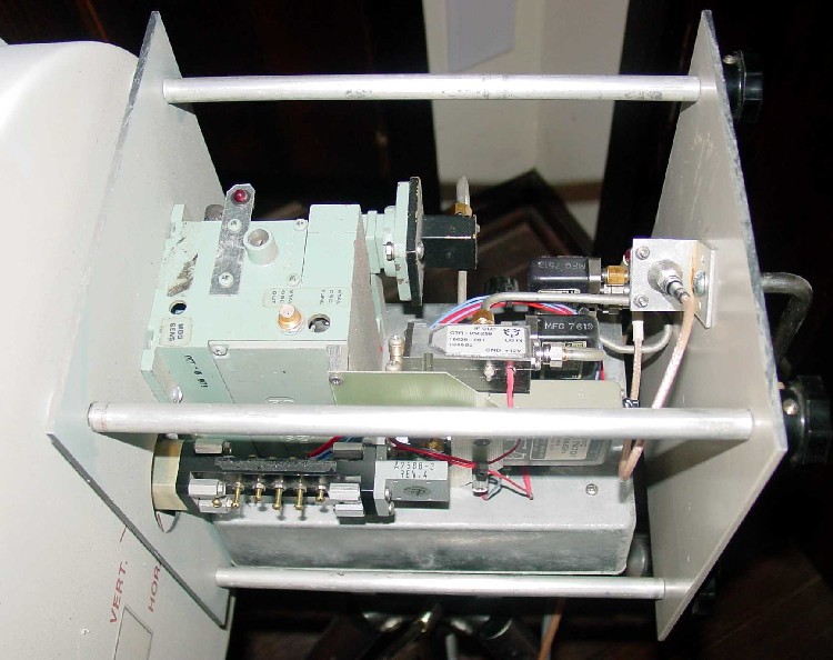
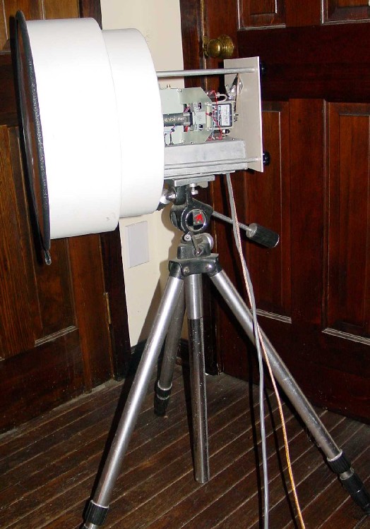
 The photo at left shows the overall physical
configuration of the transverter. The antenna is a commercial 23 GHz unit with 12
inch diameter and 34 dB gain. The transverter is constructed around a die cast box
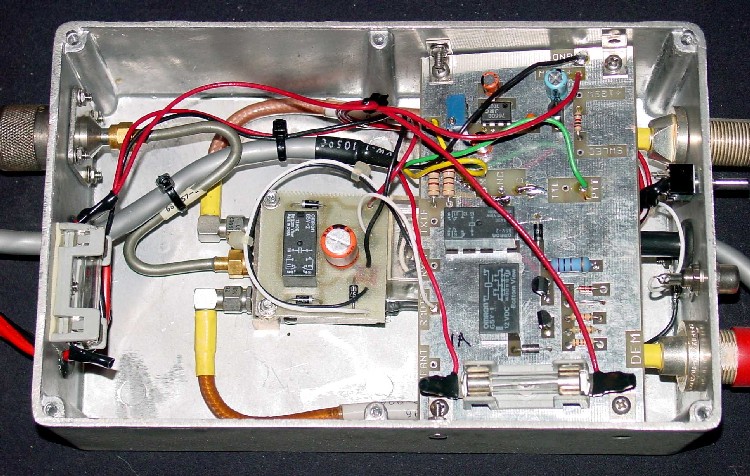
containing power supply and T/R switching. Outside the die cast box is an oven 12
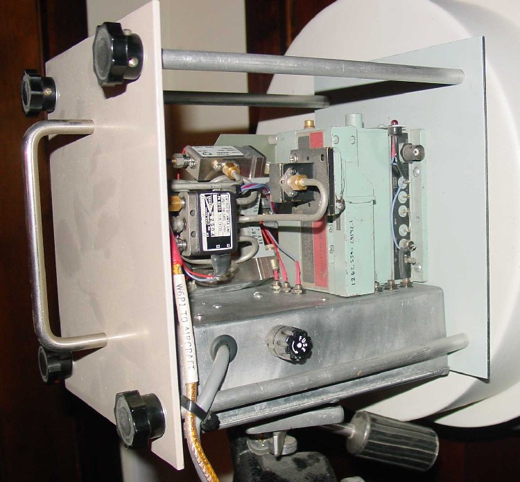
GHz LO source, up/down converters, RF/IF/LO relays, and waveguide RF filter. Refer
to the other pictures for more detailed component placement. The photo at left shows the overall physical
configuration of the transverter. The antenna is a commercial 23 GHz unit with 12
inch diameter and 34 dB gain. The transverter is constructed around a die cast box
containing power supply and T/R switching. Outside the die cast box is an oven 12
GHz LO source, up/down converters, RF/IF/LO relays, and waveguide RF filter. Refer
to the other pictures for more detailed component placement.The LO operates at half the injection frequency and is crystalled for a nominal 1262 MHz intermediate frequency. The up/down converter modules are commercial surplus providing +20 dBm transmit output and 5 dB noise figure, both as yet unverified by measurement. (I am still collecting instrumentation for 24GHz.) The switching power supply runs from a nominal 12 volts and provides -20 V for the LO source, -24 V for the relays, and +5 V for the PA stage. An LED indicator is connected to the LO source "alarm" terminal to provide a quick way to adjust the LO for proper lock condition. A solid aluminum bar reinforces the lid of the die cast box. A 1/4-20 UNC threaded hole in this bar allows for use with a standard photographic tripod. |
|