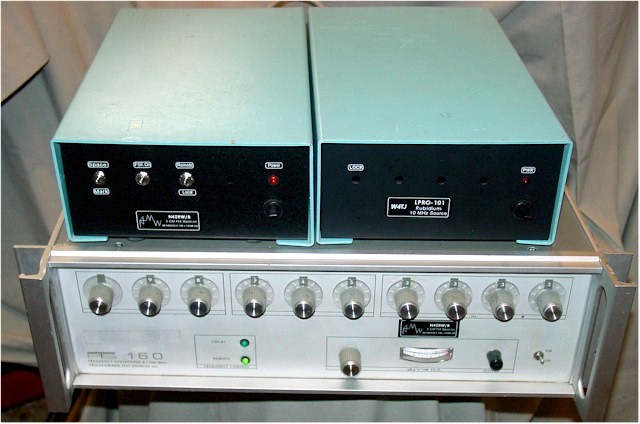
I currently have a beacon running on 10368.280, locked to a GPS reference, as well as all the bands from 144-2304 currently, all GPS locked. I have committed to describe my beacons at the Southeast VHF Society conference in April 2010. I want to demonstrate a beacon at the conference. What I came up with is the Micromega Source with a 12 slot waveguide antenna. I modified the source to accept an external reference input instead of the crystal (see below). I picked 10368.260 which, multiplying 105 times in the source, requires an external reference frequency of 98.7543333 MHz. I obtain that frequency from a PTS-160 synthesizer, which generates the needed frequency down to 1/10 Hz resolution. The synthesizer has an internal TCXO, which is pretty good, but I am using an external 10 MHz reference. This can be derived from a GPS receiver, but for my demonstration at the conference I plan to use an Efratom LPRO-101 Rubidium standard. A picture of the synthesizer, control box and Rubidium is above.
The left blue box is the controller, containing a 24 volt power supply, the ID-O-Matic keyer and power and control switches. The -24 volts is connected to a BNC jack through a Z-144 RF choke for connection th the RF head.. Another BNC jack, which connects to the synthesizer 98 MHz output, is connected to the -24 volt jack through a 0.1 mF capacitor. This is the bias tee network. The Identifier is powered from the synthesizer 5 volt connection through a 4 conductor cable. The three other connections are ground, remote programming enable and the FSK keying signal (more on that later). Switches are provided for power, remote/local synthesizer control, FSK on/off, and manual mark/space selection.
The other blue box contains an Efratom LPRO-101 Rubidium source and a 20 volt power supply. Thanks to W4TJ for the loan of the LPRO-101. 10 MHz from the Rubidium disciplined source is brought out to a BNC jack on the rear of the box. Using the Rubidium to provide an external reference for the PTS-160 synthesizer produces an accurate frequency compared to my GPS reference, but the Rubidium is not quite as clean sounding. Two LPRO-101s were tried with the same results.
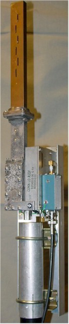
The demonstration beacon uses a bias "tee" to combine the -20 volts for the Micromega source and the 98 MHz reference frequency so that a single RG-58 run is all that is needed going up the tower. I feed -24 volts into the coax and use a 7920 regulator at the Micromega end to provide the -20 volts. A Picture of the RF head is at right. The bias tee and regulator are built into the blue Pomona box.
How do I modulate this? CW is out of the question because the source does not like being keyed on and off. Also, keying the 98 MHz reference would cause the source to lose lock and sweep around. So FSK is my solution. The PTS synthesizer remote programming port is easily set for the desired frequency, a matter of grounding the appropriate pins on the interface connector. To FSK the synthesizer, I simply toggle the appropriate BCD input bit(s). The HamGadgets ID-O-Matic keyer I am using has an active low output, which I connect to bit 1 of the 10 Hz decade connections on the programming port. The 10 Hz times 105 equals 1050 Hz frequency shift. This produces a nice clean sounding FSK signal.
Click here to hear a sample of the actual beacon signal, running with a GPS reference.
|
Modifying a microwave source to use an external reference signal |
|
To modify a Frequency West or other similar microwave source for external reference input, first leave the crystal in and confirm that the device is working OK and that you know what to expect when it goes in and out of lock as it is tuned. If everything is working OK, remove the crystal and mount a coaxial connector and wire a capacitor between the connector and one crystal socket pin. I use an SMA or BNC female jack and a 0.1 mF capacitor with convenient lead length to span the distance. I usually put the jack where the XTAL MON connector was. Some bricks are already set up for external reference - the ones I have use an SMB connector. To check things out, apply the nominal original crystal frequency at 10 mW to the reference input and monitor the lock voltage. Tune the cavity and look for a lock. There may be more than one. If it doesn't lock anywhere, try the other crystal socket pin. It may be necessary to peak the XTAL tune adjustment also. Once you confirm that everything is OK, you can zero in on the exact output frequency, reference frequency, and minimum level necessary for your application. I find that you can use subharmonics of the reference with sufficient level and still lock the brick, if that is useful to you. |