 The
left rack contains most of the beacon equipment. At the top is a 48
volt UPS which powers the GPS receiver. The GPS receiver is an HP
Z3801A with output on 10 MHz. This reference signal is connected in a
"daisy chain" to each reference input for all synthesizers, one per band.
The synthesizers are PTS-160, PTS-310,
PTS-500 or Rockland 5600. See below the description for each band for the
particular unit used and the details of the implementation.
The
left rack contains most of the beacon equipment. At the top is a 48
volt UPS which powers the GPS receiver. The GPS receiver is an HP
Z3801A with output on 10 MHz. This reference signal is connected in a
"daisy chain" to each reference input for all synthesizers, one per band.
The synthesizers are PTS-160, PTS-310,
PTS-500 or Rockland 5600. See below the description for each band for the
particular unit used and the details of the implementation.
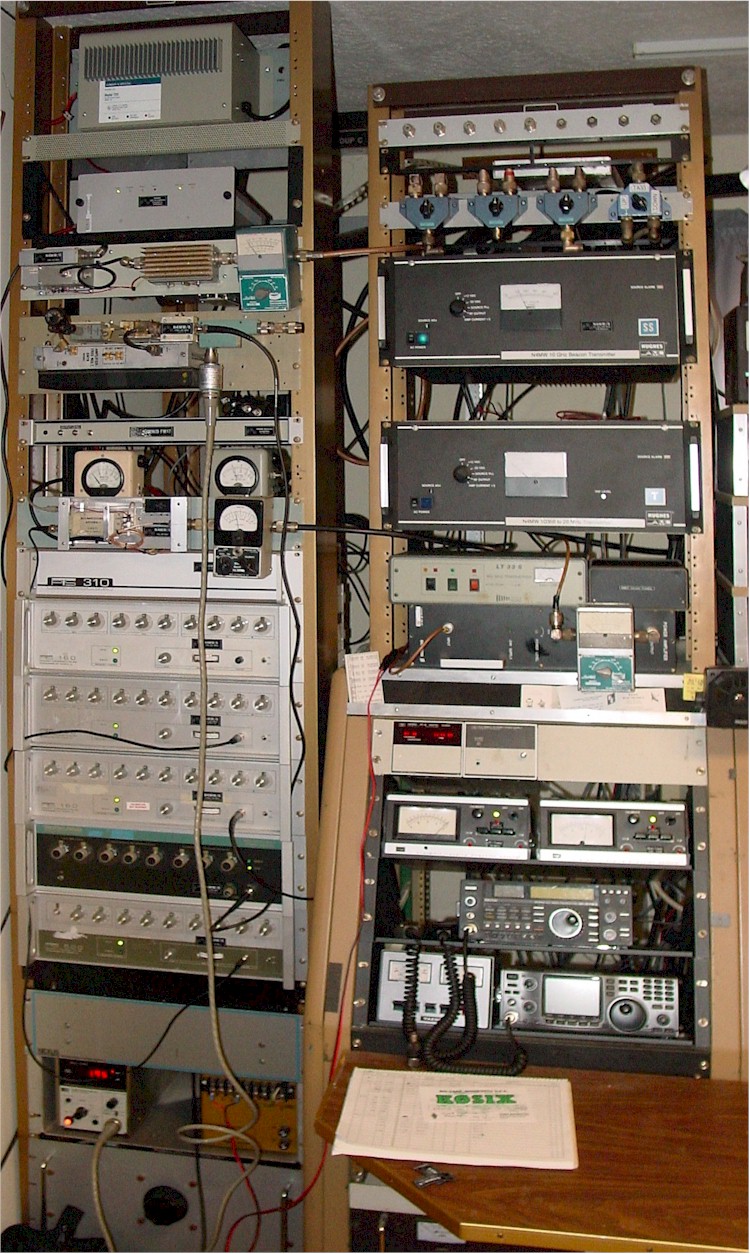
The 10 GHz transmitter is the black front panel chassis near the top of the right rack. In the left rack, just below the GPS receiver, is the 1296 transmitter, rack panel mounted. Below that is the 2304 transmitter, also rack panel mounted. The 1U rack chassis just above the two Bird power meters contains the identifier as well as both the 144 and 222 transmitters. In front of the two power meters is the 432 transmitter.
The rack also contains a 12 volt 10 amp power supply for powering units which do not have their own AC power supply. A small control box not shown contains a solid state AC relay which is used to remotely deactivate the 12 volt supply, which effectively deactivates all beacons by powering of the identifier.
Output power monitoring is provided for all transmitters using various meters shown. The HP 432B meter in the bottom of the rack shows 2304 power. The two bird meters are for 144 and 222. Bendix meters are used on 1296 and 432. The 10 GHz transmitter is built into a Hughes AML chassis, which has internal power monitoring. (Revised 27 December 2009)
Synthesizers: Several Programmable Test Sources (PTS) models are used to transfer the GPS 10 MHz reference signal to the various output frequencies needed to drive the beacon hardware. 144, 222 and 432 beacons use fundamental outputs from their respective PTS-160, PTS-310 and PTS-500 units. Higher frequency band beacon transmitters use multipliers to achieve output on the desired bands.
Most of the units have front panel controls for frequency selection and output level setting. The PTS-310 box used for 222 MHz has no front panel controls, only a remote programming connector. This model uses BCD programming, so it was a simple matter to ground five pins on the 50 pin connector to enable remote programming and set the necessary bits to program the desired frequency (really easy). There is a screwdriver adjustable pot accessible through a small hole to set the output level.
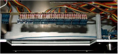 The
two PTS-500 boxes I bought recently off eBay were missing the remote
interface boards altogether. A study of the schematic revealed that
the front panel controls could be activated by supplying +5.4 volts to one
of the many dangling connections. Also needed to select frequencies
were 40 2.2K pull-down resistors, one for each bit of 10 BCD switches.
See the picture for the "fix". Also note the RCA connector installed to the
right, which is allows access to the remote level setting input if needed
later. Applying an analog voltage up to 2 volts will vary the output
level up to 20 milliwatts.
The
two PTS-500 boxes I bought recently off eBay were missing the remote
interface boards altogether. A study of the schematic revealed that
the front panel controls could be activated by supplying +5.4 volts to one
of the many dangling connections. Also needed to select frequencies
were 40 2.2K pull-down resistors, one for each bit of 10 BCD switches.
See the picture for the "fix". Also note the RCA connector installed to the
right, which is allows access to the remote level setting input if needed
later. Applying an analog voltage up to 2 volts will vary the output
level up to 20 milliwatts.
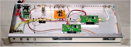 Controller
and 144/222 transmitter. The identifier is an
N0XAS ID-O-Matic
programmable keyer in beacon mode. A DB-9 connector is used to connect
to a computer RS-232 port for programming. N4MW/B repeats a simple
sequence at about 15 WPM: N4MW/B FM17kn (long dash), simultaneously on all
bands. The active low identifier output is used to switch two Darlington
output optoisolators, each driving a TIP-120 Darlington transistor current
switch. The current switches provide two positive 12 volt keyed
outputs. One drives the internal transmitters and the other is brought
out on several RCA jacks for external transmitter keying. Other
facilities are provided as follows: a red LED to monitor keying, two
potentiometers for setting the keying voltage level provided to the remote
level inputs of synthesizers which need to be keyed (no longer used).
Controller
and 144/222 transmitter. The identifier is an
N0XAS ID-O-Matic
programmable keyer in beacon mode. A DB-9 connector is used to connect
to a computer RS-232 port for programming. N4MW/B repeats a simple
sequence at about 15 WPM: N4MW/B FM17kn (long dash), simultaneously on all
bands. The active low identifier output is used to switch two Darlington
output optoisolators, each driving a TIP-120 Darlington transistor current
switch. The current switches provide two positive 12 volt keyed
outputs. One drives the internal transmitters and the other is brought
out on several RCA jacks for external transmitter keying. Other
facilities are provided as follows: a red LED to monitor keying, two
potentiometers for setting the keying voltage level provided to the remote
level inputs of synthesizers which need to be keyed (no longer used).
The 144.280 beacon transmitter consists of an M57732 device and a small circuit board containing the necessary bias and power decoupling parts. The transmitter is driven directly by a PTS-160 synthesizer operating on 144.280 MHz exactly. 10 milliwatts from the synthesizer provides 5 watts output. BNC jacks are installed for RF in and out. The antenna is an M2 Sqloop at 90 feet.
The 222.060 beacon transmitter consists of an M67723 device in a board identical to the 144 MHz transmitter. The transmitter is driven directly by a PTS-310 synthesizer operating on 222.080 MHz exactly. 10 milliwatts from the synthesizer provides 5 watts output. BNC jacks are installed for RF in and out. The antenna is an M2 Sqloop at 90 feet.
Both 144 and 222 transmitters are keyed using the bias connection to their respective boards.
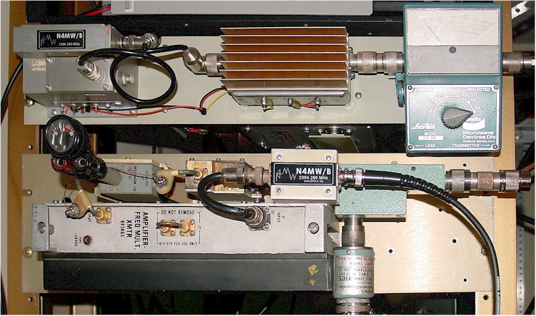
The 1296.280 beacon (top) is generated by multiplying the output of a PTS-160 operating on 81.0175 MHz by a factor of 16. A modified Frequency West source originally for 6 GHz is used with the SRD section removed to produce the desired frequency. This drives a packaged amplifier from Down East Microwave to produce 6 watts output. Keying is produced by applying a positive voltage to the first stages of the packaged amplifier. This transmitter is built on a 2U rack panel, with -20 and +12 volt output AC power supplies on the back. A Bendix Micromatch wattmeter is used to monitor output. The antenna not finalized.
The 2304.280 beacon (below) is generated by multiplying the output of a PTS-160 operating on 144.0175 MHz by a factor of 16. A multiplier/amplifier string from an AN/GRC-144 tactical microwave relay transmitter produces an output of 4 watts. Keying is produced by applying a positive voltage to a small buffer amplifier. This transmitter is built on a 3U rack panel, with +24 volt output AC power supply on the back. A small meter monitors the amplifier detector output, while an HP 432B wattmeter is used to monitor output via a 30 dB coupler. The antenna is not finalized.
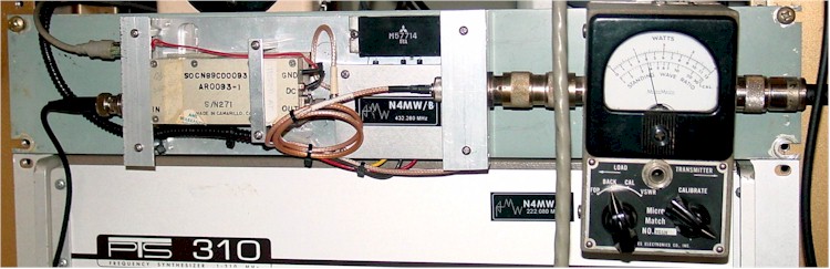 The 432.300
beacon
is generated directly by a PTS-500, which drives two amplifier
assemblies.
The first stage is keyed by a positive voltage. The final power amplifier stage is
a M57714 device and a small circuit board containing the necessary decoupling parts (built and originally used for W4HHK/B), producing 10
watts output. +12 volt power is provided from the common system supply.
A Jones Micromatch wattmeter is used to monitor output. The antenna is an M2
Sqloop at 90 feet.
The 432.300
beacon
is generated directly by a PTS-500, which drives two amplifier
assemblies.
The first stage is keyed by a positive voltage. The final power amplifier stage is
a M57714 device and a small circuit board containing the necessary decoupling parts (built and originally used for W4HHK/B), producing 10
watts output. +12 volt power is provided from the common system supply.
A Jones Micromatch wattmeter is used to monitor output. The antenna is an M2
Sqloop at 90 feet.
![]()
![]() The
903.280 beacon is generated by multiplying the output of a PTS-500
synthesizer operating on 451.640 MHz by a factor of 2.
An amplifier stage is keyed by a positive voltage and also serves as the
multiplier. The power amplifier is
a Quintron paging transmitter, producing 50 watts output. The Quintron has
self contained power supplies, status monitoring and metering. The
antenna is not finalized.
The
903.280 beacon is generated by multiplying the output of a PTS-500
synthesizer operating on 451.640 MHz by a factor of 2.
An amplifier stage is keyed by a positive voltage and also serves as the
multiplier. The power amplifier is
a Quintron paging transmitter, producing 50 watts output. The Quintron has
self contained power supplies, status monitoring and metering. The
antenna is not finalized.
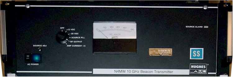 The 10368.280
beacon
is generated by mixing a 10.5 GHz signal with a sample of the 144 MHz
beacon, then filtering the lower sideband product on 10368.280 and
amplifying to provide power output. A Frequency West source driven
by a PTS-160 at 103.064314 MHz produces a 102 times frequency of 10512.560
MHz. This is combined in a mixer with 144.280 MHz sampled from the two
meter beacon, then filtered to produce a 10368.280 MHz output which
automatically follows the beacon keying. The 10 GHz transmitter is
built into a Hughes AML chassis, which has internal power supply, source
locking, PA current and power output monitoring. The
original Hughes PA is used to produce about 2 watts. The
antenna is a 24 slot WR-90 fed with 90 feet of EW-90 waveguide.
The 10368.280
beacon
is generated by mixing a 10.5 GHz signal with a sample of the 144 MHz
beacon, then filtering the lower sideband product on 10368.280 and
amplifying to provide power output. A Frequency West source driven
by a PTS-160 at 103.064314 MHz produces a 102 times frequency of 10512.560
MHz. This is combined in a mixer with 144.280 MHz sampled from the two
meter beacon, then filtered to produce a 10368.280 MHz output which
automatically follows the beacon keying. The 10 GHz transmitter is
built into a Hughes AML chassis, which has internal power supply, source
locking, PA current and power output monitoring. The
original Hughes PA is used to produce about 2 watts. The
antenna is a 24 slot WR-90 fed with 90 feet of EW-90 waveguide.